PC-6002: The Pixels - Part 1
Toolbox
The most important tool you need is a good emulator! Here are two excellent emulators with all necessary settings and files as well as a collection of PC-6001 games and demos for testing here:
- PC6001VW3: Full featured accurate emulator with a built-in debugger and many useful tools.
- iP6+: Light-weight emulator, great for quick testing.
Of course both emulators use Japanese ROMs, maybe in the future if I had access to a Warka ROM chip I could dump it and use that instead. The main difference is language, the Warka had an Arabic font built-in while the PC-6001 had Japanese fonts.
Assembly programming
All PC-60 models use a Z80 processor. I found a nice tutorial online that goes through setting up and using ZASM (z80 assembler) to compile PC-6001 programs then injecting them into PC-6001 at runtime using the PC6001VW3’s debugger: http://www.geocities.jp/tiny_yarou/asmdev/asmdev.html (japanese)
This is the easiest development path for deployment, it also produces the fastest & smallest code. For actual programming though, assembly may not be for everyone.
I will cover development using z80 and ZASM in a future post.
C programming
For the next level we will introduce a C compiler that supports Z80 and integrate it into the pipeline. I am still working on the deployment pipeline but it’s already working as I managed to deploy correct PC-6001 code.
I am using SDCC with a combination of tools and scripts to compile output.
I will cover the C programming pipeline for PC-6001 in a future post.
Mode 5: The Pixels
For this trip through Pixel lane, we’ll use MODE 5 with 4 PAGES.
The main sample program this exploration is based on is written by Tiny Yarou who seems to be the most active PC-60 developer on the internet. Here’s the sample program: http://www.tiny-yarou.com/p6sample.html
The information are in Japanese of course but the BASIC code and hex code tell us everything we need.
What the sample does is use SCREEN mode 3 in PAGE 2 and 3 as a front-buffer and a sprite-buffer.
It first draws a simple sprite sheet to PAGE 3. Then switches to PAGE 2 and uses a z80 program and parameters set via BASIC POKE instructions to blit the sprites to custom X and Y coordinates.

The coordinates and size of sprites are limited by a single rule: all X values must be multiples of 8. SCREEN mode 3 is 320 pixels wide so X range must be 0 to 40.
Reverse Engineering
The BASIC code in the sample is self-explaintory, it sets up addresses, writes the z80 procedure to RAM using POKE, draws the sprite sheet, and then execute the procedure continuously.
Disassembling (and reverse engineering) the z80 procedure, I was able to learn a lot:
; PC-6001 MkII (64K) Mode 5 Page 4
; Blit function: from spritebuffer page to frontbuffer
ORG 0D000H;

; Symbol def
SPRBUF EQU 4000H
SCRBUF EQU 8000H

START:
	DI
	LD HL, 0000H	; 00GY
	LD DE, 0000H	; 00GX
	CALL MOVETOY
	LD BC, SPRBUF	; GP00
	ADD HL, BC
	PUSH HL
	LD HL, 0000H	; 00PY
	LD DE, 0000H	; 00PX
	CALL MOVETOY
	LD BC, SCRBUF	; PP00
	ADD HL, BC
	EX DE, HL
	POP HL
	LD A, 0DDH
	OUT 0F0H, A
	LD C, 14H		; SY = 20

SETUP:
	LD B, 02H		; SX = 2
	PUSH HL
	PUSH DE

HORCPY:
	LD A, (HL)
	LD (DE), A
	SET 5, H		; adding 32
	SET 5, D
	LD A, (HL)
	LD (DE), A
	RES 5, H		; subtracting 32
	RES 5, D
	INC HL
	INC DE
	DJNZ HORCPY
	POP DE
	POP HL
	PUSH BC
	LD BC, 0028H	; 40 is the screen width
	EX DE, HL
	ADD HL, BC
	EX DE, HL
	ADD HL, BC
	POP BC
	DEC C
	JR NZ, SETUP
	LD A, 011H
	OUT 0F0H, A
	EI
	RET

MOVETOY:
	ADD HL, HL
	ADD HL, HL
	ADD HL, HL
	LD C, L
	LD B, H
	ADD HL, HL
	ADD HL, HL
	ADD HL, BC
	ADD HL, DE
	RET

END
Here are some observations:
- Procedure program address is at 0xd000 (notice that 300 bytes are cleared in BASIC starting at that address)
- PAGE 2 and PAGE 3 memory addresses are set (SCRBUF and SPRBUF), these are effectively the pointers to the first pixel in each. When number of pages is set to 3 instead of 4, the memory map is different and PAGE 2(SCRBUF) and PAGE 3 (SPRBUF) start at 0x4000 and 0x0000 respectively.
- Notice DI and EI in the beginning and end effectively disabling hardware interrupts. Otherwise if an interrupt happens while the procedure is running, registers will get messed up. When I tried removing those I either got random looking noise and glitching or a crash then restart of the PC.
- The last label ‘MOVETOY’ simply multiplies HL by 40 (which is 320 pixels divided by 8) and that’s how many bytes in memory represent a single horizontal line in mode 320x200.
The rest is pretty straight forward assembly. What the procedure is doing on a high level is this:
- Figure out the pointer to the first pixel block in spritebuffer for the sprite and first pixel in frontbuffer to draw the sprite to.
- Loop while copying bytes from spritebuffer to frontbuffer one horizontal line at a time.
Every block of 8 pixels are represented by 2 bytes. The first is in the specified PAGE address and the second is offset by +0x2000 in memory (that’s what SET 5, H and D effectively do). The combination of the first and second bytes produces the pattern and colors of that particular 8 pixels block.
So the reason why X is limited to multiples of 8 is simply because thats how pixels are layed out in memory, if you want to change a single pixel/color from assembly you’d have to do some bit wrangling.
The way they managed to encode 8 pixels (16 color each) in 2 bytes is by cheating! Mode 3 is actually 160x200 where every pixel is doubled horizontally. As a result this is how text looks like in mode 3:

Sprite Movement
PC-6001 doesn’t support hardware sprites (as far as I know), so moving sprites around requires some trickery.
In general, there are 2 methods to do this based on what I currently know:
- Backpage/frontpage switching: this will work only in Mode 5 a(Mode 6 has single graphics PAGE). Simply clear and move sprites in the backpage then switch pages and repeat.
- frontbuffer movement: this will not look nice, but essentially clear sprite then draw it in new position. it won’t look nice because you will see the clearing and drawing.
For both methods we need a clear procedure. So I modified the sample program to do just that:
; PC-6001 MkII (64K) Mode 5 Page 3
; Blit Zero function: clears pixels from screen
ORG 0D080H;

; Symbols table:	LO	 HI
; SCRBUF ZP00		D08B D08C
; 00ZY				D082 D083
; 00ZX				D085 D086
; ZH				D093
; ZW				D095
; Screen width/8	D0A5 D0A6
; Pattern value		D098
; Attrib value		D09C

; Symbol def
SCRBUF EQU 8000H

START:
	DI
	LD HL, 0010H	; 00PY
	LD DE, 0020H	; 00PX
	CALL MOVETOY
	LD BC, SCRBUF	; PP00
	ADD HL, BC
	LD A, 0DDH
	OUT 0F0H, A
	LD C, 14H		; SY = 20

SETUP:
	LD B, 02H		; SX = 2
	PUSH HL

HORCPY:
	LD (HL), 0FFH	; Write pattern value
	SET 5, H
	LD (HL), 0FFH	; Write attribute value
	RES 5, H
	INC HL
	DJNZ HORCPY
	POP HL
	PUSH BC
	LD BC, 0028H	; 40 is the screen width
	ADD HL, BC
	POP BC
	DEC C
	JR NZ, SETUP
	LD A, 011H
	OUT 0F0H, A
	EI
	RET

MOVETOY:
	ADD HL, HL
	ADD HL, HL
	ADD HL, HL
	LD C, L
	LD B, H
	ADD HL, HL
	ADD HL, HL
	ADD HL, BC
	ADD HL, DE
	RET

END
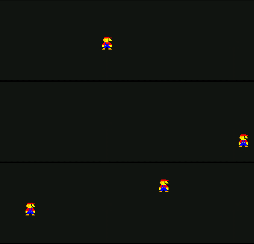
I created a minimal test for the two procedures:

For the next part, I’m going to write a tool to help import PNGs into N66 BASIC then code a movement function that does the blitting and clearing automatically.
blog comments powered by Disqus